Tuesday, December 31, 2013

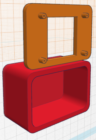
With the 4D display mocked up (roughly), it was clear there would be some interference inside the display case.  For the first prototype, it'll be slightly wide due to the control board, and now it's about 2 mm taller to take the display's PCB bezel into account.  (NOTE: The 3D model I designed of the OLED-128-G2 for prototyping is now available to the community in the TinkerCAD Gallery as well.)

The "cutaway" (actually the "hole" option) of TinkerCAD is very useful for seeing inside enclosed spaces.


It's also handy for measuring where to put features like micro-SD card slots.


While most of these models are white because it helps to have as much brightness and contrast as possible during on-screen designing, the finished product will most likely be black - (but a huge number of color options are available in ABS filament, and plastic paint would make the options virtually limitless).

I'm also making big changes to the power supply, to make it even more robust in light of the vagaries of car-supplied power.  The main capacitor is being super-sized to a 63V-capable unit that can withstand load dumps from the alternator, but which at a size larger than a typical C-battery requires a lot more room in the enclosure, and doesn't leave much room for anything else - so the enclosure is now expanded, and the capacitor has to come off the board and be wired to it, with a mounting method similar to that shown.  The middle capacitor is also being changed to *lower* its voltage in line with the original project instructions in "Practical Arduino", to minimize ESR (equivalent series resistance).


With these changes, the revision number of the project file increments to 0.3x and the Mouser projects have been updated to reflect the component changes.  There are no wiring changes so the 0.2x PCB project on OSH Park remains applicable.

Monday, December 30, 2013

PDuino's power supply is now prototyped in TinkerCAD in 3D, which is helpful when designing the enclosure and testing for interference between the components.


The combined power supply and Arduino enclosure is also prototyped, despite some loss of progress due to TinkerCAD crashes, and the power supply fits nicely (upside down) over the top of the Arduino.  I had a nice transparent cut-away view but that's when TinkerCAD crashed (again).


Progress continues on the display enclosure as well, but a lot of work remains to be done there as it's the most visible piece.  This will most likely be a real "prototyping" approach using physical models for fit and finish.

All of the 3D models are shared on TinkerCAD, search for "PDuino", or use the Convenient Links I added on the right side of the blog, which will be updated to always point to the latest revision of design files for the project.

Sunday, December 29, 2013

A nice borrowed enclosure for the Arduino, and a *very* rough beginning of an enclosure for the display.  All done and shared in TinkerCAD(.com).  The Arduino enclosure I'm considering (below) is borrowed from the MK II project shared here, but I want to ensure it will be moisture-resistant.


UPDATE: OK, a little more work, and a little more acceptable, but still far from "finished".  Gotta get more familiar with TinkerCAD.


Friday, December 27, 2013

I realized that the 0.1X Control Board, at 60 mm, is slightly wider than the prototype 4D display, which is *tiny*. The 4D Systems uOLED-128-G2's display area is only 27 mm square, and the whole display unit including screw mounting holes is only 45.56 mm wide. (Product info here).

I redesigned the control board to add some mounting holes, update the revision to 0.2x, and most importantly to be much more compact, especially in width, going down to exactly the width of the display unit (once the header tab is broken off the left side).

[Pictures removed, due to design being deprecated.]

Thursday, December 26, 2013

I took some time to add more documentation to the power supply circuit board, and a pre-drilled mounting hole in each corner.  I updated the version number of the power supply board to 0.2x, and then re-exported the project to OSHPark.com.

None of the wiring changed of course, and initial tests of the 0.1x board indicate success, e.g. when powered by a 12V battery, the circuit board puts out exactly 5V, and holds that 5V for several seconds after power is removed.  Under more of a load, that several seconds will probably be reduced to milliseconds, but that's all we need to power down the Arduino and display anyway.  My apologies for the "vertical video syndrome".

Wednesday, December 25, 2013

I had a bit of time to solder up the first power supply board this afternoon.  Everything fit well, except for the large screw terminal, the holes for which I had to bore out slightly.  I think it came out pretty well.


I don't want the smaller screw terminal to be top-entry (with the screws being hard to reach on the side), so I've updated the Mouser project to include a side-entry terminal (with the screws more accessible on the top).  All of the parts for the power supply components are available on Mouser, in a project saved here.