Monday, October 28, 2013

I've been reading up on power supplies for Arduinos installed in vehicles, and apparently cutting the power is bad in several ways.

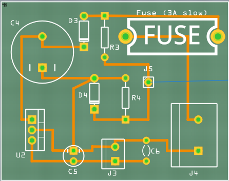
So, I've borrowed the work of several others who were gracious enough to post their work online, and re-designed a printed circuit board that will provide enough power after the key is turned off to let the Arduino and 4D display power down gracefully.  The basic design I believe is from the "Practical Arduino" book, but "Sanja" was kind enough to make it available as a project and download for Fritzing here.  I did a lot of trace re-routing and fitting for my purposes, and version 0.1x is re-designed to my satisfaction in Fritzing and ready for manufacture.


Thursday, October 24, 2013

Just finished the code for setting the screen contrast, and am looking into an auto-dimmer function as well, which would probably be easier than tapping into the light dimmer because the brightness settings would be quite different. 

Wednesday, October 23, 2013

One more change, I decided to reconfigure the board to include headers to connect from inside to outside the eventual enclosure.  That way, it can be a "pop-off" design.


Tuesday, October 22, 2013

The button array, previously only in breadboard format, has been "virtualized" in Fritzing, and the printed circuit board (PCB) has been designed, both bare and "populated".  It's ready for manufacture.

NOTE: As there will undoubtedly be many revisions of circuit boards, the latest revision will always be linked to in the upper right of the blog.


Monday, October 21, 2013

Interface basic functions are complete. While the menu options themselves will change over time, the basic functions of scrolling the menu selector, performing the correct function when selected, and going "back" are implemented.


Sunday, October 20, 2013

The first version of the software is written, just enough to achieve a boot load on the 4D display (pass-through powered by the Arduino itself), to display the Splash, About and Main Menu screens.


Saturday, October 19, 2013

The button "array" is configured and wired up, and work continues on the menu system.


Tuesday, October 15, 2013

The project coding has been started and is now hosted by Atlassian's BitBucket.

Monday, October 14, 2013

The first draft of menus is done, and are designed for a planned 4-button interface with Up, Down, Back, Select being the primary ones.


Sunday, October 13, 2013

Here is a very crude mockup of what it would look like inside the gauge cluster.  This would only work for manual transmission vehicles, as that position in the lower half of the tachometer is taken up by the gear selector indicator (PRND321) with the Tiptronic (automatic) cars.


If it is not an option to mount the gauge within the instrument cluster, a small custom enclosure could be mounted on the fixed portion of the steering column which would place the screen right between the speedo/tach, and which would more easily facilitate multiple "buttons" to manage the interface. I think this would look a little more "tacked on", but it would make it much more accessible to people as not everyone wants to cut a hole in their tachometer.  Those things are $900+ to replace.

Saturday, October 12, 2013

Working with 4D's Workshop IDE, I've mocked up the beginnings of a Splash and About screens, primary menus (not shown), and the rudimentary beginnings of a Boost gauge. The font is as close as I could purchase to the existing gauges, being Eurostile Extended Black. For now, I call it "PDuino".


Friday, October 11, 2013

This blog will document my research into- and work toward- an electronic multi-function gauge for the Porsche 968, (and any other vehicle that is pre-OBD-II).  The interior of the 968 is particularly spartan in terms of room for adding things - witness the many failed attempts at the perfect cup holder. I'll add the components I am researching currently in this and subsequent posts.

I am currently leveraging the ideas of several people who kindly posted their ideas on the web, although they unfortunately did not post the real guts of their solutions. Credit where due to winmutt on superturbodiesel.com, and his thread.

After much research into Raspberry Pi, Netduino, Beaglebone and others (including a trip to NYC Maker Faire to see them all in action) I have decided my first foray will incorporate an Arduino microcontroller (Uno R3 specifically) to read the voltages from any sending units and to allow a platform for incorporating accelerometers, GPS sensors, wireless radios (Bluetooth, WiFi), USB and ethernet communications, and a wide variety of input devices (joysticks, keyboards, etc.)


Output will initially be driven to a 4D Systems 1.5" OLED capable of displaying text, graphics and video. I'm hopeful there is a place to mount this or a similar display unit flush behind the existing gauges (similar to in-dash displays in many modern cars), perhaps at the bottom of the tachometer. Being an OLED display, it requires no backlight and is extremely thin. I still need to do measurements and find out what kind of room is back there, and hopefully there aren't any warning lights embedded there either.